In Brief:
The Floor Unit contains the carrier for the plate with the drive- and sensing coils.
It has facilities to precisely adjust the height and level and to adjust the centering in two perpendicular directions.
Materials and dimensions are not critical. Change them to your preferences, but avoid ferro-magnetic materials.
Contents:
The Adjustment Mechanism for North-South and East-West.
Height and Level adjustment.
Adjustment Procedure Height and Level.
Adjustment Procedure Center.
Some photos
East-West and North-South adjustment.
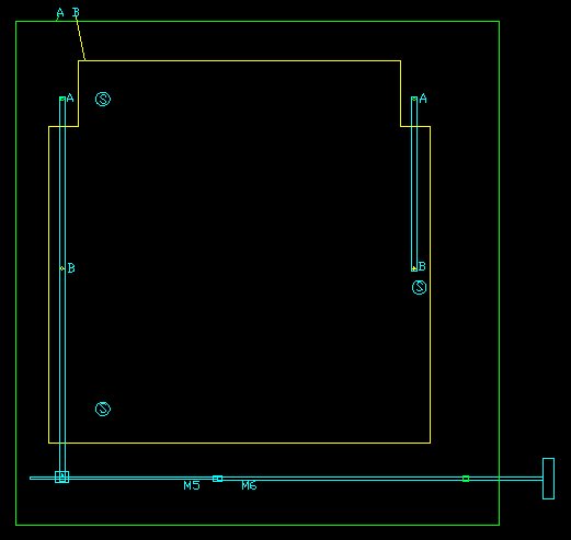
fig 1. Principle of adjustment.
We have a baseplate A (green) and a sliding plate B (yellow). The sliders S are hard-plastic furniture sliders mounted on the bottom of B.
Two aluminium strips can pivot at the points A, attached to the baseplate. At the points B the pivots are fixed to the sliding plate with a screw.
It will be clear that plate B can only move in one direction and cannot rotate. I use 3 sliders so the plate cannot wobble.
On the long arm sits a small aluminium block with an M5 threaded hole, in which an M5 threaded rod can turn. Halfway the M5 rod is coupled to an M6 rod which passes throug an M6 threaded hole in a stand fixed to the base plate. On the end is a knob to rotate the rods.
The pitch of M6 is 1 mm and M5 has 0.8 mm pitch. So when the rod is turned 1 revolution the M6 rod will move 1 mm, while the block with M5 moves 0.8 mm in the other direction. The result is a displacement of 0.2 mm of the block, and approximately 0.1 mm for plate B.
A similar mechanism allows adjustment in the perpendicular direction.
The benefits of this approach are that a very precise adjustment can be made and that it is practically free of any play or hysteresis.
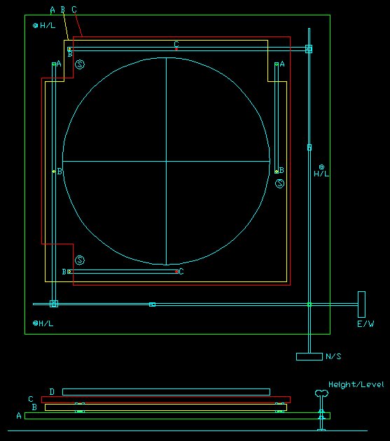
Fig 2. The complete setup.
The baseplate A (green), the East-West sliding plate B (yellow), the North-South sliding plate C (red) and the coil assembly (cyan / circle).
The furniture sliders are fixed to the bottom and top of B, nearly on the same positions.The aluminium strips (not drawn in the crossection) all sit between B and C.
Mind the shapes of plates B and C, some corner pieces are taken away to allow the pivots A and to reach the screws B while assembling the whole.
You also might need holes in the center to pass cables through.
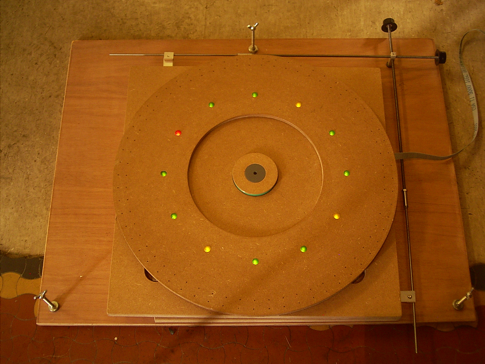
Fig 3. The complete floorunit.
Height and Level adjustment
 Height and Level adjustment Is done by 3 M6 threaded rods going through
T-nuts in the bottom of plate A. (only one shown in fig 2)
Height and Level adjustment Is done by 3 M6 threaded rods going through
T-nuts in the bottom of plate A. (only one shown in fig 2)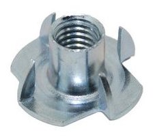
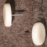
Fig 4. T-nut. Fig 5. Furniture glider.
The rods have a winged nut at the top and a sharp tip at the lower end where they rest in something on the floor. I used 3 coins with just-not-through drilled holes.You may glue them to the floor for accurate repositioning. Above plate A are a washer and a nut to fix the screw after adjustment. When not fixed the screws will wiggle.

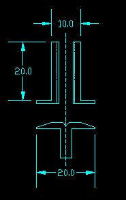
Fig 6. Parts for the Vrijland Pendulum. Fig 7. Bus and Rest.
For the Vrijland Pendulum I made slightly more sophisticated parts. The rods go through threaded busses which are much longer than the T-nuts and hardly allow wobbling. The busses are glued into plate A. The floor rests sit in 8 mm holes drilled into the floor, and filled with plaster, which hardens while plate A is in position. The holes are pre-drilled with plate A as a template, when it is as good as possible centered below the bob.
The floor rests have a center hole with a 90° cone made with a center drill. The rods also have a 90° tip.
When the floor unit has to be removed for other activities in the chapel, the remaining rests will stay in place and nobody will stumble over them, nor dislocate them.

Fig 8. Support during hardening of the glue.
As I wanted the rods to be well perpendicular to plate A, I loaded the busses during hardening of the glue. As the busses stand out from the top of plate A, I used a large nut for support.
Adjustment procedure Height and Level.
Set the EW and NS adjustment rods to the mid position.
Place the Floor unit visually such that the still hanging bob is as good as possible above the center of the coil assembly. You should be able to do that within 1 mm.
Adjust the height for the desired distance to the bob. Measure level in perpendicular directions on the coil assembly and adjust with the appropriate winged screws. When the adjustments are done fix the winged screws with the nuts above plate A.
Adjustment procedure Center.
Launch the bob in North-South direction. Observe the passage times from the zero-detection coil and make them as equal as possible with the N/S adjustment knob. Adjust in the direction which gave the longest passage time.
Then launch the bob in East-West direction. Observe and adjust the same way with the E/W knob.
After that: do'nt touch it anymore and keep cats and dogs away.
Some Photo's
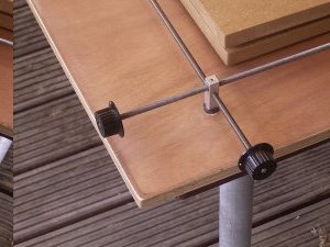
Fig 9.
The stand and the knobs for adjusting the center in East-West and North-South direction.
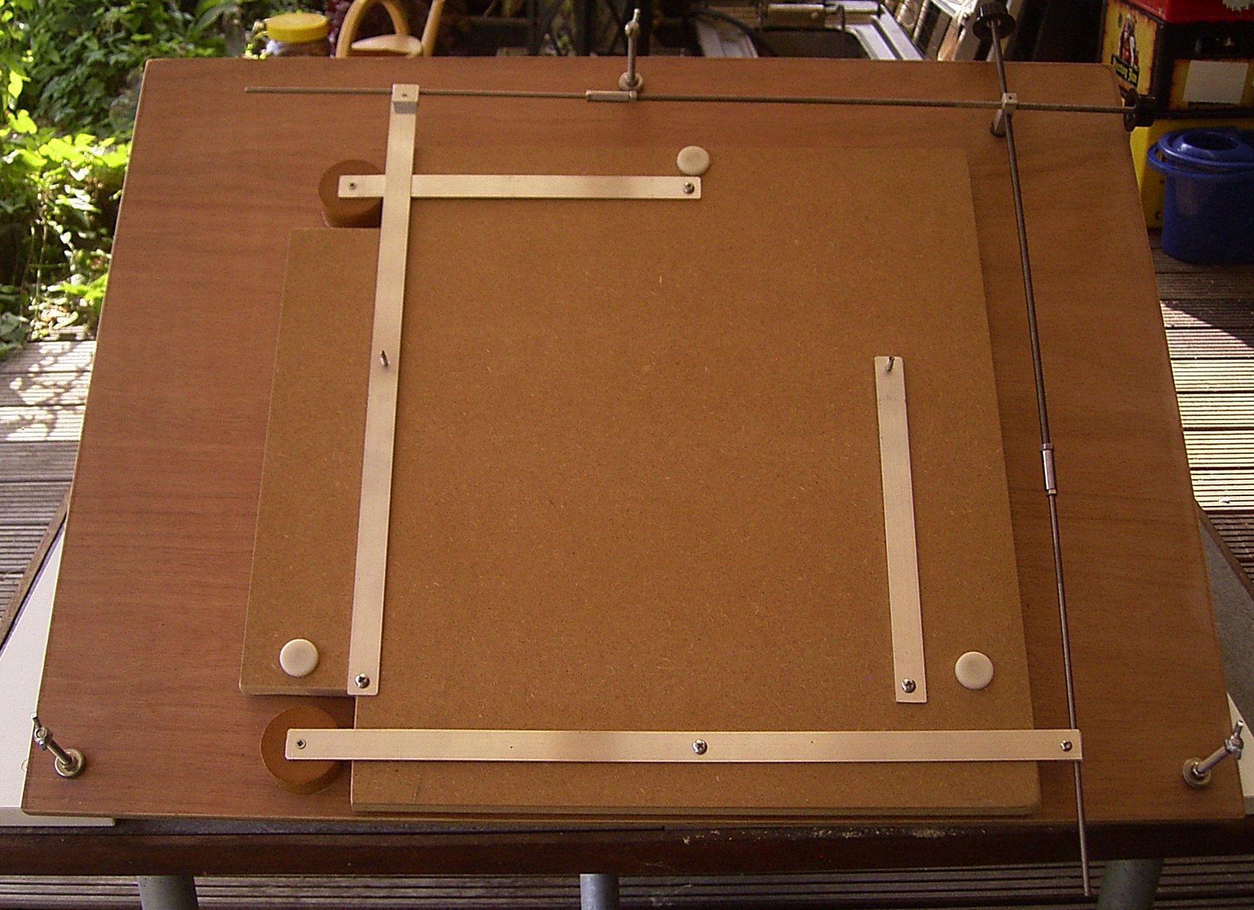
Fig 10.
Plate A and B and the complete adjustment mechanism. Plate C is to be mounted on the upright screws in the middle. That cannot be done in this situation, so the the strips for C (vertical on the photo) were taken apart and mounted to the bottom side of plate C. After that plate C was placed in the correct position and the lower ends of the strips can be screwed to plate B through the holes in plate C.
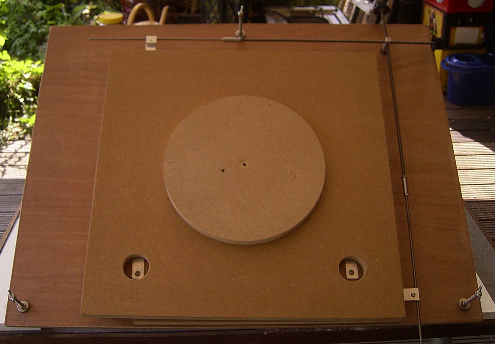
Fig 11.
Plate C is also mounted. Note the holes through which the scews can be accessed.
The circular plate is the carrier for the coilformers, not yet machined in this stadium.
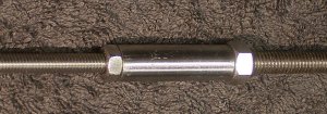
Fig 12.
The coupling of the M5 and M6 rods is done by a rather long M5 coupling nut (the cylindrical part) in which I made M6 over about half the length.
Fix the rods firmly with ordinary nuts.
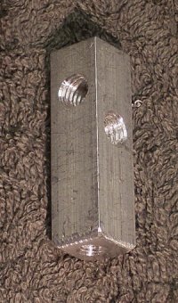
Fig 13.
The M6 rods go through this stand which is mounted on plate A with an M4 screw.
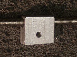
Fig 14.
The M5 part of the rod goes through this block which is fixed to the long aluminium strips. (2x) The mounting hole was threaded M4. The fixing screws were secured with lock bond. Do not fix them too tight, they must rotate a little during adjustment, but there should not be any play.